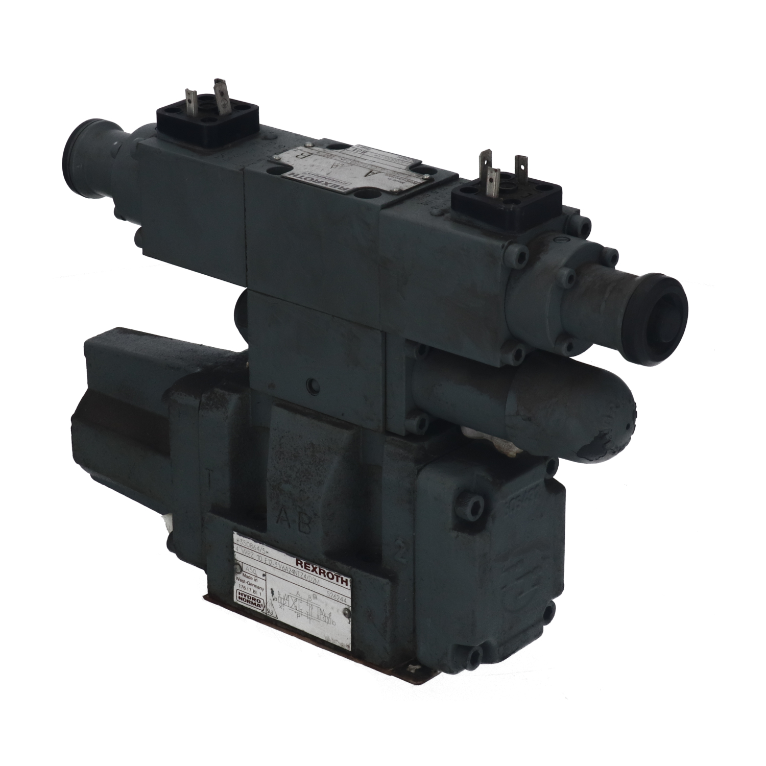
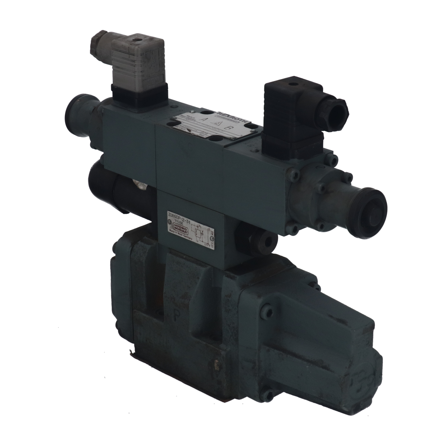
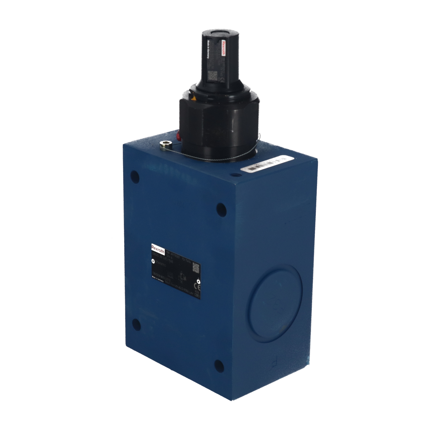
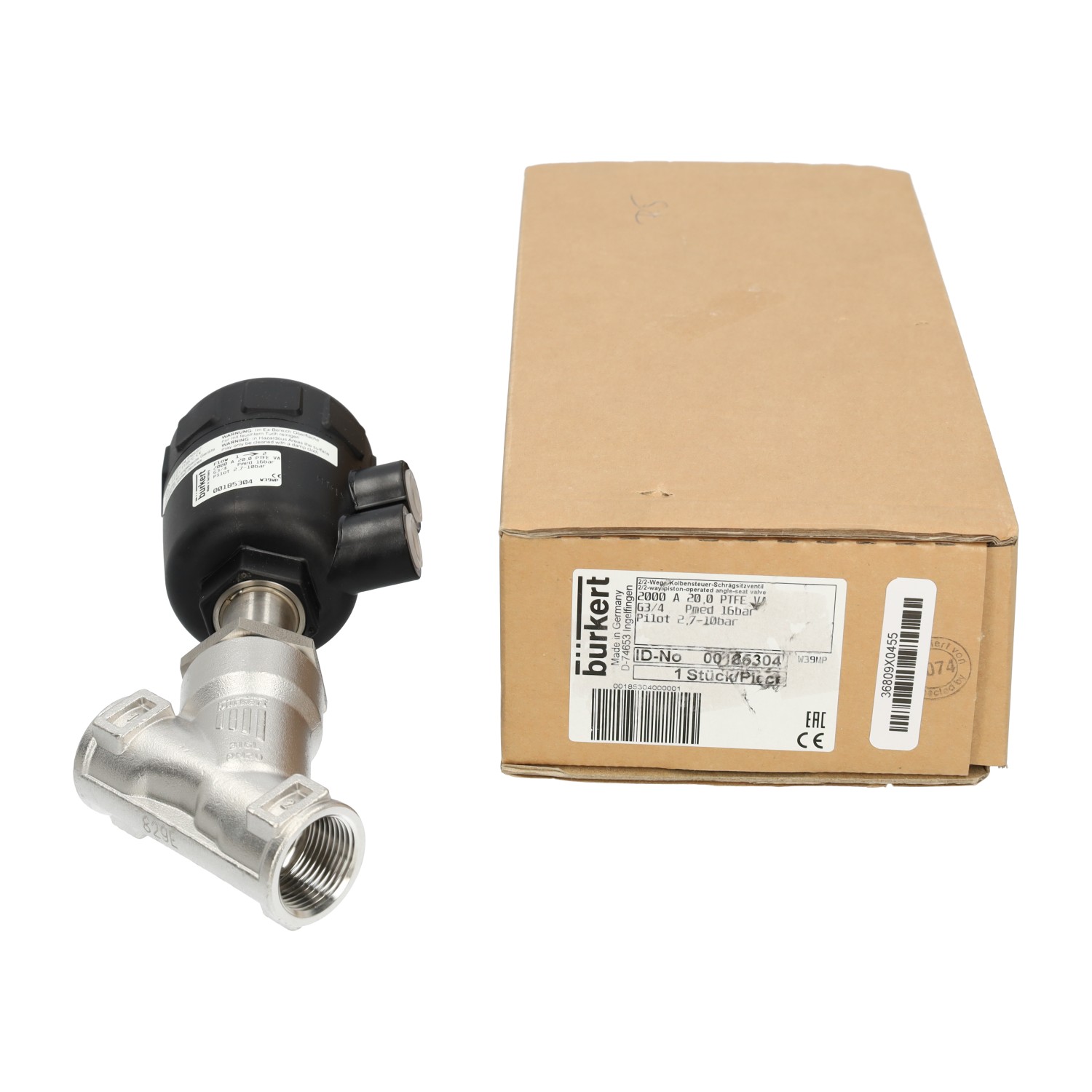
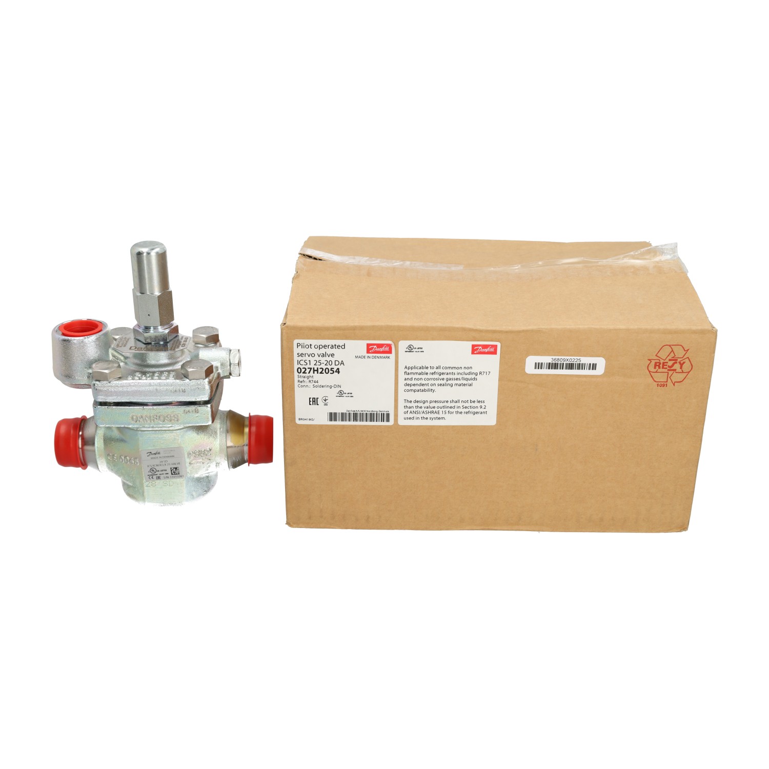
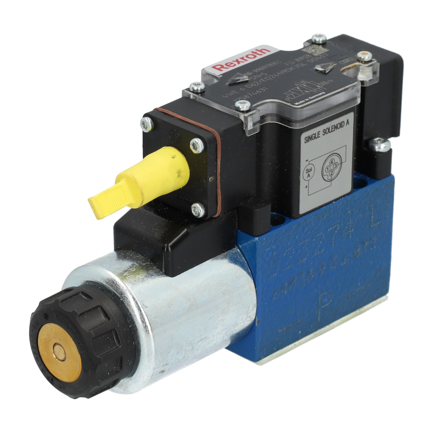
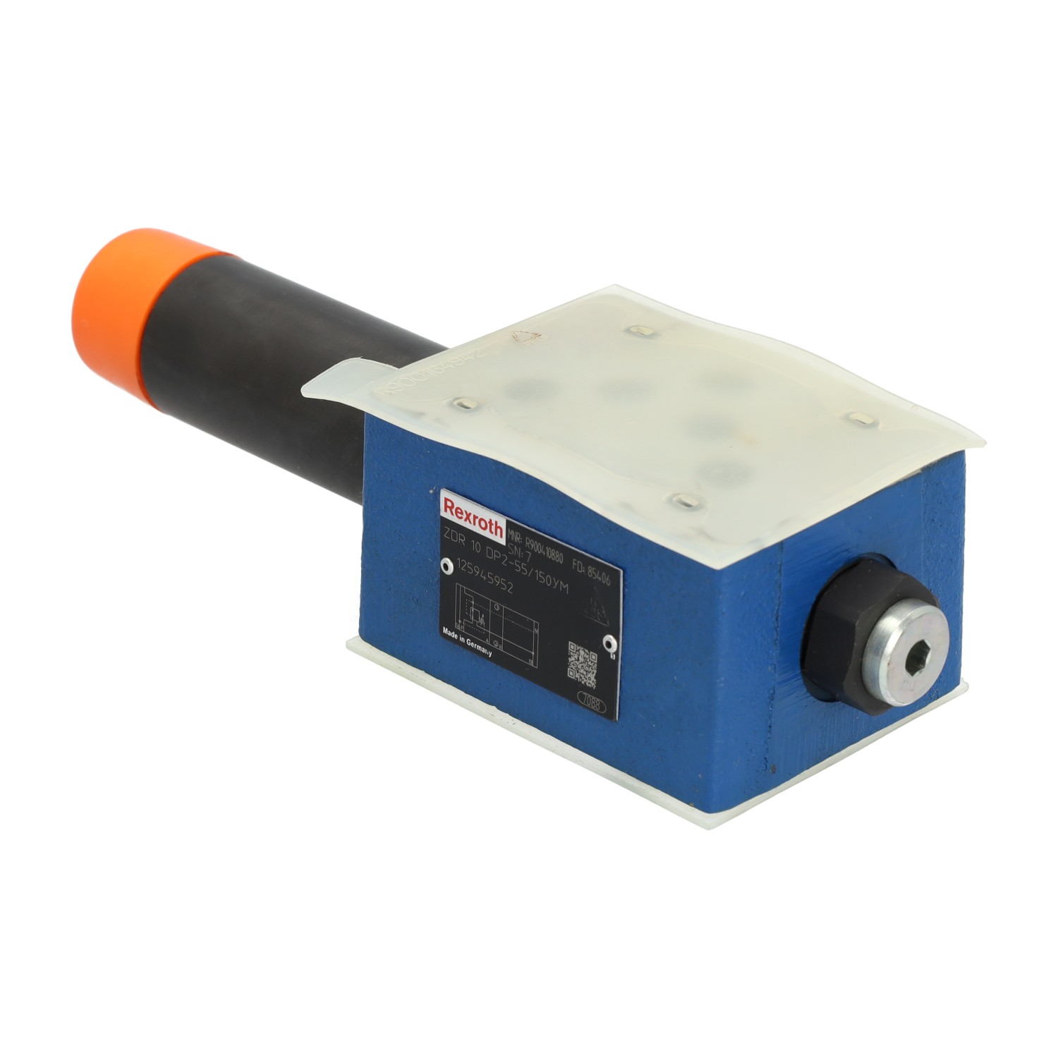
Hydraulic valves and valve blocks
Use of pneumatic valves
A pneumatic system consists of interconnected parts which use compressed air or gas for conveying and regulating energy. Such systems are employed in numerous industrial applications. Pneumatic directional control valves, also known as air-operated valves, are an important part of this kind of configuration. They are usually regulated by the same compressed air stream which propels the pneumatic system. Activation can occur in a number of manners. The valves can be manually controlled, air piloted or solenoid operated.
Subdivision of pneumatic valves
There are several ways of subdividing the different valve types further. One way to classify them, is to consider the number of entry and exit ports they have. Another feature by which you can identify them, is the mechanism which is responsible for closing and opening the ports. Then there is the number of available switching positions, and finally, a breakdown is possible based on the valve position in un-actuated state. Some important considerations when selecting a valve are the number of possible valve positions, ports and flow paths.
Two-Way directional control pneumatic valves
Two-way pneumatic valves allow air to travel in two directions, via two ports that can be either open or closed. Air cannot flow through this valve type when the ports are closed. When they are open, air can travel from the first port, via the valve, through the second port in the other direction.
Three-Way directional control pneumatic valves
A three-way pneumatic control valve is equipped with three ports. Each of these ports fulfills a specific role. One of them is an exhaust exit. The second one is linked to the airflow. The third port, finally, connects the valve to a device, such as an actuator. When the exhaust exit port is closed, air reaches the connected device through the valve. When the port that is connected to the device is closed, the exhaust can be vented. This type of directional control valve is, for instance, often used in combination with double acting cylinders.
Four-Way directional control pneumatic valves
A four-way pneumatic valve comprises four individual ports. Two of them are linked to actuators, one is linked to a pressurized airflow, and the last one functions as an exhaust route. Four-way pneumatic valves are among the most commonly valve types used in pneumatic systems. The reason for this, is that the separate paths allow the valve to reverse motor or basic cylinder motion very effectively. When a fifth port is added to this valve design, a five-ported four-way valve is the result. This specific valve type is mostly applied to acquire double pressure. Depending on the exact technical configuration and requirements, one of two pressure types can be selected and harnessed. Furthermore, the other port can serve as an auxiliary exhaust port.
Spring offset pneumatic valves
The classification type of this variant of pneumatic valve alludes to the way air flow direction is changed. For instance, the valve of a two-way pneumatic valve can be open, in which case air flow is permitted. The valve can also be closed, resulting in a blockage of the air flow. In other words: airflow is either allowed or prevented. A valve spool is brought into position by an actuator, which sets the port into the open or closed state. To enable the pneumatic valve to return to its original position, this valve spool must first be released. This is achieved by a spring mechanism. Two-way directional valves which incorporate this configuration, are known as spring offset pneumatic valves.
Open or closed resting state
While the connected actuator is idle, bidirectional spring offset valves can occupy one of two positions: either open or closed. In open resting state, air is allowed to pass freely into the connected device via the valve. Airflow is blocked in a closed resting state. In other words, unless the device is switched on, there is no air in motion.
Pneumatic solenoid valves
A pneumatic solenoid valve renders manual or pneumatic control of pneumatic circuits unnecessary. These electric directional control valves require only an electrical input and air pressure for piloted valves. A small electrical current is used to transmit a signal to the spool or poppet mechanism after which the valve is either opened or closed. Some examples of voltages, often used to control the coil, are 12 VDC, 24 VAC, 24 VDC, 120 VAC and 240 VAC. Because of their uncomplicated design and operation, programming and installing these valves in a broad range of applications is easy. They can be installed in inaccessible, remote locations which makes them suitable for use in off-site operations. Tubing and of course electrical connections are necessary for installing a pneumatic solenoid valve in your system.
Air pilot operated pneumatic valves
Air-pilot operated valves need an external air source to function. Air pressure is exerted on the diaphragm or piston to manipulate the valve. They are available in either a single or dual air pilot control variant and both poppet and spool designs are available. Furthermore, versions with or without priority function can be used. A priority function secures a default position if two signals would be received at the same time.
Valve blocks and manifolds
Combination and base units are available to fully configure a pneumatic system to very specific requirements. A combination unit consists of both a valve block and a manifold. This manifold is a mounting block which enables two or more valves to be fitted together in a pneumatic assembly. It serves as a focal node for a sole air supply which is divided among all valves. In most cases manifolds are base mounted but DIN rail configurations exist as well. The two main manifold variations are the modular and single-piece designs. Modular types are quite flexible, since only a single valve per base is involved. This allows for an easy implementation of a blend of valve sizes. The most common used models, however, are the single-piece models made of steel, aluminum, or cast metal. These are very suitable for high-pressure applications since they incur minimal leakage.

